
Wisdom: How to save grief & time
Leave this part at the top. All new animated GIFs must go below it.
Before starting a new part of a project that will take several steps:
Write down the steps in bullet form. It is so easy to neglect one step. There are so many facts to learn within SketchUp.
Moving guardrails up steps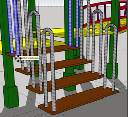
In this set of exercises, you have a set of guardrails on the lower steps. You will create new sets of guardrails on the precise locations on the next 3 stairs. This is how to do it:
-
- With the Select tool, single click on one guardrail. With the shift key down, click on the guardrail of the other side of the step.
- Hover the Move tool over a corner of the step.

- Drag your mouse cursor up and click ALT (Ctrl in Windows) to replace the handrails on the lower step.
- Click on the same corner of the next step. Those guardrails will now be established on the next step.
- Do the same exercise for each of the steps.
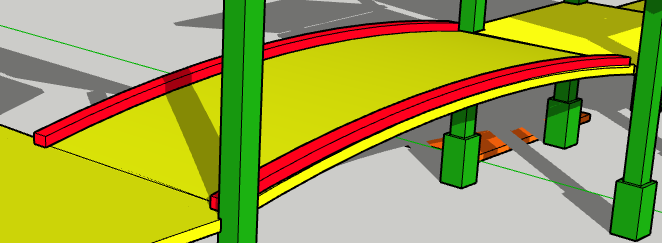
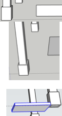
Railings sinking deeper into arc support
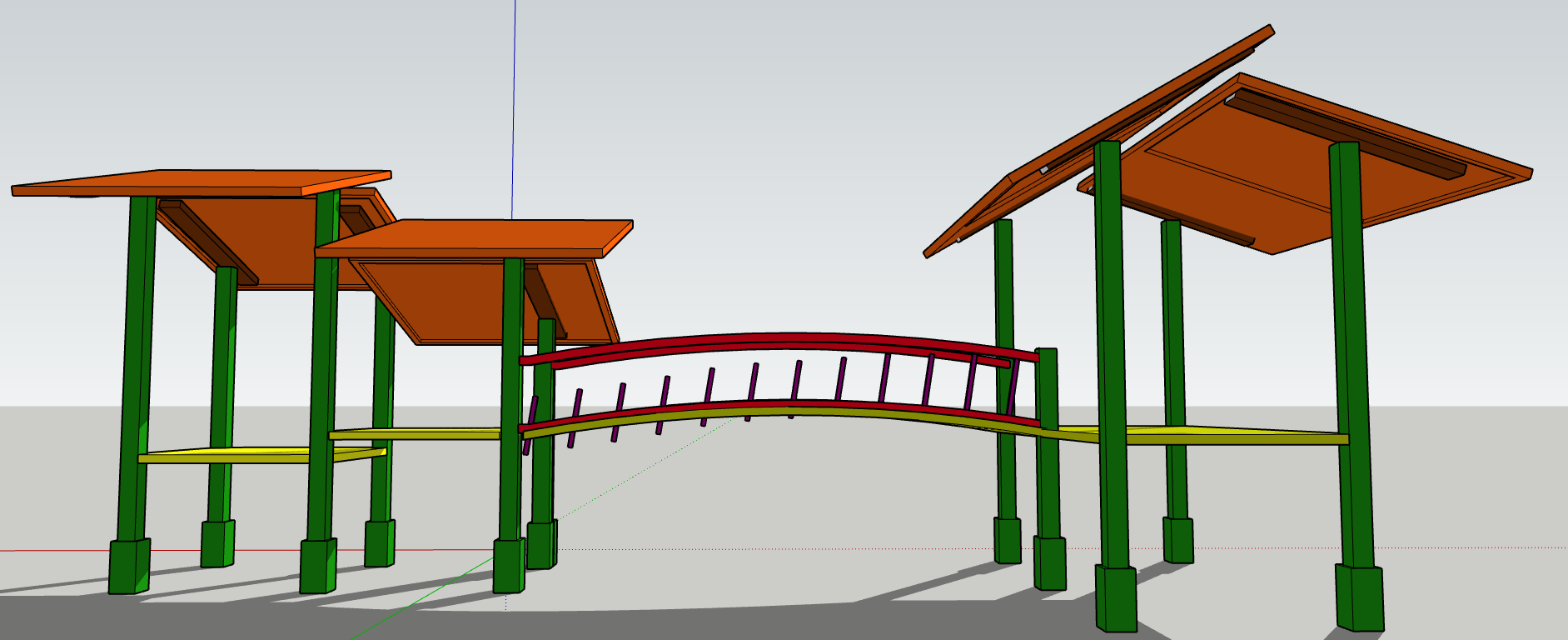
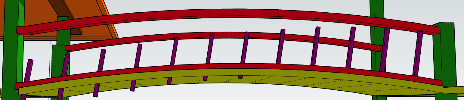 As you can see from the images, the railings were sinking deeper & deeper into the red lower arc support. I explain below how to quite simply prevent this problem:
 Assuming your rail is a component, place it in position in front of your first guide line.
- Zoom in to make dragging simple. All you need is 2 guide lines on your screen. Z is the hot key for Zoom.
- After clicking Select, click the rail once.
- Using the shortcut M to choose the move tool, hold your cursor at a lower corner of the rail.
- Drag the rail towards the next guide line.
- At some point, press the ALT key (Ctrl in Windows) to place another copy of the rail at the point from which you began dragging.
- Let go of your left mouse key after the rail is in position.
- Click on the Select icon and click once on the last rail. (In all likelihood, the last rail will remain selected. You will not have to click on the Select icon.)
- Holding your cursor on the lower corner of the rail, move it towards the next guide line.
- Repeat until the railing work is finished.
- Note that you do not have to hold right onto the corner.
- You may be able to hover over the corner and then move you cursor away as you see in this animated GIF.
Copying the edge of a component
 In this exercise you have a solid bridge connecting two platforms within a playground set. You will want to take a tiny slice of the edge of the bridge, move it away from the bridge and pull it out 3″. You will make it into a component and add it to the bridge in two places. This will add some decoration to the bridge.
These are your steps:
- After the bridge has been made into a component, place it in edit mode. Use the Select tool to double click on the bridge.
- Click once on the edge of the bridge. Dozens of tiny blue dots should show up on the edge.
- Cmd C to place a copy of that edge into your clipboard.
- Click you mouse on the screen a distance away from the edge.
- Cmd V to paste a copy onto your computer screen.
The new component
- Use the Push/Pull tool to pull the edge out 3″.
- Change the new curve into a component.
- Move it onto either side of your bridge.
- Give it a bright colour like you see in the screenshot of a tiny part of the playground.
Creating a curved playground slide
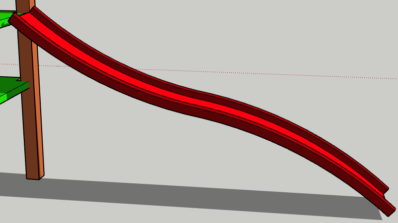 In this exercise you will use the Follow Me tool. You will create a curved line on a single plane. You will use the hot keys M for Move and L for a straight line. You will use these arrow keys: Up to move along the blue axis, Right Arrow to move along the red axis and Left to move along the green axis.
To create the slide, we need to make 2 things: A curved line that is on a single plane and a shape representing a cross section of the slide. The curved line will be on a red-blue plane. The cross section shape will be at a right angle to the end of the curved line. These are your steps:
-
 You should be looking almost straight ahead at your red axis. The slide will be attached to the 2 posts you see in the animation. So, rotate those 2 posts are almost one over the other.
 - Using L right arrow for the horizontal lines and L up arrow for the vertical lines, draw a rectangle like the one in the animation. It will be 6 – 8’ wide. (L is the hot key for the straight line.)
- Keep drawing the straight lines until the rectangle is filled in. In the animation note that, after the second point was made, the cursor was moved to hover over the bottom of the post for a second or 2. That was to inference that point as the bottom elevation of the rectangle.
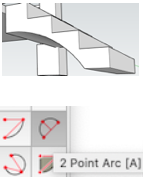
- Now you can draw the curved line on a plane that is on the red and blue axes. Click on the 2 Point Arc tool.
- Draw an arc that curves downward similar to the one in the animation.
- Click on the end of the arc and make another arc in the opposite direction. It should be a light blue color.
- Make sure the second arc is light blue before you click the left mouse button. That is to make sure that the line continues at the same angle is it transitions to the second arc. Otherwise there would be a straight line on the slide and the children would feel a bump at that point.
- Run your Erase tool through the corners of your rectangle so that the only thing left is the curved line.
- Clicking on the end of the curved line, draw a rectangle along the green axis.
- Draw another smaller rectangle within the larger rectangle.
- Erase the line on top of the smaller rectangle to reveal a U shape.
 Enlarge that U shape so that you can draw 2 point arcs on the ends.
- Draw the arcs and Erase the 3 lines above it.
- Now both ends of the U will have curved ends.
- Click on the Zoom Extents tool to get an overview of where you are at.
 Click on the Follow Me tool.
- Click and hold the Follow Me tool over the slide cross section.
- Keeping the left mouse button held down, drag the cross section up to the top of the curved line.
- Erase the line at the left end of the slide.
- Using the Select tool, select the entire slide moving from left to right.
- Use the Move tool to make the top of the slide line up with the platform.
- Click on the Paint Bucket tool.
- Colour the slide.
Creating monkey bars for a playground
Assume that you have an existing playground complex. You want to add a set of money bars. These 3 animated GIFs along with the bulleted text will show you how to do it.
If you are fairly new at SketchUp, there are 3 things introduced here that you may not know about:
- There are hot keys for various tools. For instance, to move you may want to press the letter M instead of clicking on the Move tool.
- The arrow keys can be use as direction keys. Push M right arrow to move in the red direction; M left arrow to move in the green direction; M up arrow to move in the blue direction.
- You don’t always have to click the Move tool on an object to move it. In the animated GIF below we hovered over a selected object for about 2 seconds. Then held the Move cursor above the object and pushed the right arrow. We moved the pipe to another post without touching the object with the cursor.
Step #1 — Connect 2 posts with a long pipe
 Select the SketchUp Circle tool.
- Hover over the centre of the top end of a post for a second or 2. (You may have to enlarge the post to do that.)
- Move the cursor straight down a short way.
- Click on the post and move the cursor to enlarge the circle.
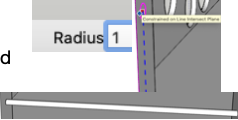
- Go to the radius box in the lower right hand corner.
- Enter 1″.
- Select the Push/Pull tool and press the green arrow.
- Pull the circle to the next post, ending on the edge of the post to get the distance correct.
- Click the Select tool and draw a box around the pipe going from left to right. That selects it.
- Right click on the pipe to change it into a component as you see in this animated GIF.
Adding a second long pipe
 Click on the Select tool and then on the long pipe.
- Click on the Move tool and then the right arrow.
- Hold the Move cursor over the selected pipe for 1 or 2 seconds.
- Move the cursor to above the pipe and press the right arrow.
- Holding your left mouse button down, move the pipe towards the destination.
- Press the ALT key (Ctrl in Windows) to reproduce a pipe in the original position.
- Position the pipe in the middle of the post like you see in the animated GIF. (You may have to enlarge your post in order to do that.)
Adding the short bars
-
Enlarge the posts so that you can add a circle to the centre.
- Click the Circle tool and click on the post.
- Drag the circle out and then enter 0.5″ in the radius box.
- Click the Push/Pull tool.
- Drag the circle to the first post.
- Click the Move tool and then the Left arrow.
- Move the bar to the right.
- Then push the Up arrow to centre the bar over the long pipe.
- Enlarge the bar and Pull the other end into the other pipe.
- Single click and then right click on the bar to make it into a component.
- Single click on the bar and click on the Move tool. Press the Left arrow.
- Drag the bar to the right a short ways and press the ALT key (Ctrl in Windows).
- Press x12 Enter or any number that you feel would for sure fill the pipes with adequate bars.
- For each extra bar you have left over on the right, click once and delete.
Making a Foot Bridge with Rotate Tool
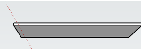
Start with a plank and an arc
 Use the Rectangle tool to create a long narrow rectangle. (You may have to click the Up arrow to make sure the rectangle is on the red-green plane.)
- Use the Push/Pull tool to make the rectangle thicker.
- Use the Paint box to make the plank brown.
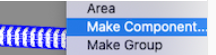
- Using the Select tool, triple click on the plank. Then right click on it and select Make Component.
- Give the component a descriptive name such as Bridge Plank.
- Click the 3 point arc tool.
- Click on the edge of one post.
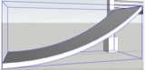
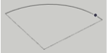
- Click between the 2 posts to determine the lowest point on your arc. (You may have practice a bit
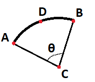 to determine the ideal best point. If it is too low, the arc may double back on the posts. If it higher, the centre point of the arc could be either too low or too high. In this image, the centre point is at C.)
 - Ideally the 2 end points of the arc will on the same elevation. In the foot bridge below, they were not on the same elevation. That resulted in using 3 planks to the left of the centre plank and 4 planks to the right.
Creating the foot bridge
 With the Select tool, select the plank. (If you don’t have the plank, click on Window > Components and drag the image of the plank onto your screen.)
- With the Move tool, hold the cursor over the tiny green circle that represents the centre of the end of the plank.
- Drag the plank onto the lowest point of the arc. The tiny green circle must rest on that point.
- Select the Rotate tool and drag the cursor along the arc.
- At one point you will see 2 faint lines leading up to the centre point of the arc. There will be a tiny green circle at the centre point.
 As you hover the cursor up towards the centre point, it will become invisible.
- Hover around where you saw the centre point last and it will show up again.
- Click on that point, let go of the mouse button and move your cursor down to the plank.
- Click on the tiny green circle at the end of the plank.
- Move the cursor so that the plank mover along the arc.
- Press ALT (Ctrl in Windows). Then a second plank will show up at the bottom of the arc.
- Click the mouse button to lock the plank in place at the top of the arc.
- Press /3 Enter. There will be 3 planks to the left of the centre planks.
- Choose the Select tool again.
- Click once on the centre plank.
- Click the Rotate tool.
- Move the cursor along the arc.
- After the arc centre point shows up, take note of its location. It will disappear until you hover the cursor over the centre point.
- Click on the centre point.
- Click on the centre of the end of the plank.
- Move the cursor so that the plank moves along the arc.
- Press ALT (Ctrl in Windows).
- When the higher plank it at the highest point, click the mouse button.
- Press /4 Enter.
- There will be 4 planks to the right of the centre plank.
Note that the layout of the planks was not balanced. That was because the 2 ends of the arc were not at the same elevation.
Foot bridge with balanced layout
In this animated GIF we begin by drawing proper guide lines. Then both arc ends will be at the same elevation. The lowest point on the arc will be at the centre. There will be the same number of planks on each half of the bridge.
We are clicking the right arrow to move along the red axis, left arrow for the green axis and blue for the up-down axis.
The 2 posts are 4 feet apart along the green axis. The pairs of posts are ten feet apart along the red axis.
 Click the Tape Measure tool on the centre of the post. If you start from the corner of the posts you will not get a guide line. You may have to enlarge the post to be able to select the centre point.
- Drag it up 4′ to create a horizontal guide line. Then the end points of the arc will be at the same elevation.
- Drag the Tape Measure tool up 2′ to help find the lowest point on the arc.
- Measure the distance between the two posts along the red axis. It is 116″ in the animated GIF. Half of that is 58″. So, from the centre of a post drag the tape measure out 58″. Where the 2′ and the 58″ guidelines cross you will find the lowest point on the arc.
- Click on the 3-point arc tool.
- Click on the left hand end of the 4′ guideline.
- Click on the lowest point of the arc.
- Click on the right hand end of the 4′ guideline.
- Click on the Select tool and then click on the plank.
- With the Move tool, move the green circle on the end of the plank to the lowest point of the arc. (Watch carefully how this is done in the animated GIF.)
- Move the Rotate tool along the arc and note where the centre point of the arc is. (In the GIF it is above the screen. So, it was necessary to use the Hand tool to drag the lowest point of the arc to the bottom of the screen.)
- Hover the Rotate tool along the arc to get the angle of the arc into your computer’s memory.
- At a few points on the arc the Rotate tool will display a tiny green circle at the arc angle.
- Slide your cursor up and click on that green circle.
- Slide your cursor down and click on the green circle in the middle of the bottom of the end of the plank.
- Without touching the mouse button, begin to move the cursor along the arc.
- Before reaching the top of the arc, press ALT (Ctrl in Windows) to reproduce another plank at the lowest point of the arc.
- You do not want to leave too much space between the planks. So, to reproduce more planks, experiment with different choices — /6, /8 or /9. (In the GIF we used /9.) Note that if there is too much space when you use /6, you can immediately use /8. That will erase the 6 planks and replace them with 8. Try it and see how well SketchUp does this for you.
- With the Select tool, select the lowest plank again.
- Using the same system as the system above, insert the final nine planks.
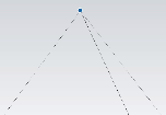
Creating a pyramid shape with Offset & Move
 In the animated GIF you see here, we took the top of 4 pillars and created a pyramid on top of them. These are the steps for doing that:
- Click on the Rectangle tool and, inferencing to the corners at the top of some posts, draw a rectangle.
- (Note that you cannot quite finish a perfect square. You have to finish off your square by pushing up and then pulling the sides out.)
- Using the Push/Pull tool, pull the rectangle up 2 inches.
- Use the Push/Pull tool to extend the rectangle beyond the posts. Try to make a square shape.
- Use the Select tool to select the top face of the square.
- Use the Offset tool to drag out a little perimeter around the outside of the square.
- Click outside the square to deselect the square entirely.
- With the Line tool, connect the opposite corners of the square in order to find the centre.
- Press the Up arrow so that the Move tool will be moving straight up in the next step.
- With the Move tool, drag the pyramid straight up from the centre of the square.
- These exercise is from a SketchUp for Schools tutorial. Find the tutorial here.
Turning the pyramid into a component
- Using the Paint Bucket, colour the pyramid.
- Using the Select tool, move left to right to select the entire pyramid.
- Right click on the pyramid.
- Click on Make Component.
- Give the component a descriptive name.
- Any time you have to use that component, go to Window > Components and drag the appropriate component onto the SketchUp screen.
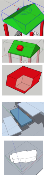
Cut off pillars going through a roof
 In the animated GIF here, all of the pillars are the same height. Consequently, some of them go though the slanted roofs. Here is how to cut off the tops of the pillars.
- Rotate and enlarge the underside of a roof.
- Double click a pillar that is going through a roof.
- Draw a straight line that exposes a tiny bit of the pillar.
- Double click on that pillar above the straight line.
- Push on the part of the pillar with all of those tiny dots. Inference to the far edge of the pillar.
- Look at the animated GIF. The pillars no longer stick through the roof.
Using a remote component to remove material
 Remove material from a copy of a component. Use the original component to do that. In the animated GIF we removed part of the roof. This is how to do it:
- Draw a line on the original component to represent how much has to come off the roof.
- Using the Select tool, double click on the original component.
- Triple click the same component to make it editable.
- Draw a line over the original straight line. That isolates and therefore selects that part that must be removed.
- Use the Push/Pull tool to remove the selected geometry.
- Notice that the end of the roof is removed at the same time.
- If things do not work out, remember this: To completely remove the content, the face that you push must be parallel with the face on the opposite side of your model. If any lines divide the opposite face, you need to erase those lines before you can cut a hole through your model.
How to use the Move tool to rotate an object
 These are the steps for rotating an object with the SketchUp Move tool:
- With the Select tool, select the object.
- Hover over a red plus sign with the Move cursor.
- Holding down the left mouse button, rotate the object.
- Experiment by hovering and rotating with different red plus signs in different objects.
- Note that before you can find any red plus signs, you CANNOT have selected the object in any way with the Select tool.
How to make multiple copies of a component
 This is how to create some decoration on a pillar and create 5 more copies:
- Make a 12′ high pillar.
- Draw a circle extending beyond the bottom of the pillar.
- Using the Move tool, extend the circle up 12″.
- With the Select tool select the entire pillar.
- Right click on it and select Make Component.
- Give a descriptive name to the component.
- Using the Move tool and the left arrow, begin to move the pillar along the green axis.
- Press ALT in a Mac or Ctrl in Windows to paste a copy in the original position.
- Enter 4′ or 48 into the Distance box and press Enter.
 Rotate your work 90 degrees.
- Holding the Shift key down, use the Select tool to SINGLE click on the unselected pillar. (At first a triple click seemed to work. However, a single click does it. More clicks would enter the component and edit it.)
- Using the Move tool and the right arrow, begin to move the 2 pillars along the red axis.
- Press ALT in a Mac or Ctrl in Windows.
- Enter 4′ or 48 into the Distance box and press Enter.
- Key 2x into the Dimension box and click Enter.
How to copy an object
 This is how to copy an object using the ALT key (Ctrl in Windows):
- Using the Select tool, select the entire object from left to right.
- Right click on the object and make it a component. (It is best practice to name the component.)
- Double click the object to make it editable.
- Use the Select tool and select it.
- Use the Move tool to move it.
- After you have begun moving it, press the ALT key (Ctrl in Windows).
- With the Select tool, click outside of the objects to deselect them.
- Now you have 2 copies.
Create a roof with hip ends
 As you can see from this animated GIF, we are drawing a roof with 30 degree slopes. Then, at the end, we will make a hip end at the front of the roof. These are the steps:
-
- Click on the Protractor tool icon.
- Hold it on the face that will have a gable. Here it is green. Keeping the green protractor, held it over a corner so that the centre is over end point. Click.
- Move the cursor to the perimeter of the protractor. Click.
- Clicking made the protractor click at every 15 degrees. Move it up to 30 degrees and click to make a 30 degree guideline.
- Do the same from the opposite corner.
- Using the Pencil icon, make a triangle by connecting the guidelines like you see in the animated GIF above.
- Using the Push/Pull tool, push to triangle to the far end. Stop as you click the end point.
- Erase the guidelines.
We will now finish off the hip end
- The front triangle is called a gable end. We want to change that to a hip end at a 30 degree slope.
- With the Protractor tool, hover over the side of the house. You will notice that the protractor is red.
- As you can see in this animated GIF, you click at the point where the centre of the protractor is on the corner of the roof.
- Click on the perimeter of the protractor to make the guide lines snap to 15 degree intervals.
- Create a 30 degree guideline.
- With the Pencil tool, draw a solid line along the guideline. Precise distance is not important.
- Press the right arrow to make a red HORIZONTAL line.
- Hover to the right from the solid line. A red solid line will form.
- Connect the right end of the red line to the point in the corner of the roof.
- That will form a triangle that is at a 30 degree slant.
- Press the left arrow so that the point from the top of the gable and will start moving in a straight line to become a hip end.
- Hover over the 30 degree triangle so that the gable end will stop when it is at 30 degrees.
- Erase the triangle and you are finished.
Draw a line parallel to another line using inferencing
To draw a line parallel to another line:
 Start by using the Line tool to make a dot at the appropriate place.
- Drag the Pencil icon along the first line for at least 2 seconds. This is called “inferencing”.
- Holding the left mouse key down, drag the cursor over towards what would be a parallel line.
- When that line turns a magenta colour, it is parallel. You have inferred the slant of the first line to the second line.
- Hold down the Shift key and drag the line to the point you want the line to end.
- Press the left mouse button.
Selecting an end point
 You can’t select an end point with the Select tool. You must use the Move tool.
Move components within a group

This is how to move individual components within a group:
- Select all of the components to make a group.
- Click Select cursor outside of the group to deselect all components.
- Double click group to make it editable.
- Click on Move tool icon.
- Drag any components away with the Move tool.
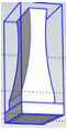
SketchUp Follow Me to Draw a 3D Wineglass
More about the Follow Me tool
Before you draw the wine glass, it may be valuable for you to know a bit more about the Follow Me tool.
To practice using the Follow Me tool, draw a rectangle and use the Push/Pull tool to draw up a box.
 Use the Line tool to draw a rectangle RIGHT ANGLED to the box. An understanding of the role of the right angle is essential. The top of the box will be selected to highlight all of the edges around the top. The Follow Me tool must be clicked at a right angle to selected lines.
- Remove part of your smaller rectangle to make for an interesting pattern. (See the long purple shape in the animated GIF.)
- Add an interesting colour to the small rectangle. Note that in the example here adding the colour was a here was a way of checking to see if the lines around the shape was complete. Obviously the lines were not entirely joined. So, the entire face of the box became purple. This was fixed by changing it to a light colour.
- Notice how at one point new straight lines were added to the shape to fill in the place where the suspected gap in the lines occurred.
- The shape was coloured.
- The Follow Me tool was selected and the shape was clicked to form the purple trim around the box.
The wine glass
-
You will need a circle for Follow Me to follow when making the wine glass.
- Scroll up to get more of a birds’ eye view of the red-green plane.
- Draw a circle on the red-green plane starting a the origin.
- Select the circle and use the Move tool to draw it down along the blue axis.
- Draw a rectangle along the red-blue plane. This will help you draw the 2D wine glass so that every line is on the same plane. If any line is not on the same plane, Follow Me will not work.
- (The entire 2D drawing will use only 2 tools — the 2 Point Arc and the Line.)
- Draw a straight line along the blue axis to a point close to the bottom.
- Draw an arc as you see in the animated GIF.
- Draw a very short straight line to the right.
- Draw an arc close to but not touching the blue axis.
- Draw a straight line up as high as the first straight line.
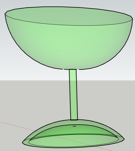 Use the Arc tool to draw the outer edge of the glass.
- Draw a straight line parallel to the red axis from the arc to the centre.
- Draw another straight line connecting to the very first straight line. (You should now have a continuous line in the shape of half a 2D wine glass.)
- Click on the colour you would like for your glass and use the slider to reduce the opacity to somewhere between 10 & 20.
- Select the circle. This will select the entire circumference for the Follow Me tool to follow.
- Select the Follow Me tool and click on the 2D wine glass. It will become a 3D wine glass.
Push/Pulling nested objects
In this animated GIF we have some nested slats on the chairs. They are components. Each chair is a component within a larger component of one table & six chairs. This is how to make each slat narrower.
-

Double click 3 times down from the table & chair group to a chair component to a slat component.
- If you try Push/Pulling the slat, you will get an error message.
- To Push/Pull a slat, simply enlarge the image of the chair and Orbit to see the bottom of each slat.
- Then Push/Pulling will be simple.
Making certain components unique
 In this animated GIF, all 8 pillars start out as ordinary components. We want to make 4 pillars wider. These are the steps:
- With the Select tool, select the 4 pillars you wish to make wider.
- With the Select cursor, right click on a pillar and select Make Unique.
- Double click one pillar to make it editable.
- You want the right half of the 4 pillars to be wider. So, with the Select tool and going FROM LEFT TO RIGHT, select the right half of the pillar.
- Use the Move tool and the left arrow to enlarge the right side of the pillar along the green axis.
Copying the pillars in the first place
 Let’s say you started with one pillar. This is how to make 7 more identical pillars:
-
- Make sure you initial pillar is a component. With the Select cursor, select the entire pillar going from left to right.
- Right click. If it is a component, you will see “Edit Component”. If not, click on “Make Component.”
- Now make a second copy of that pillar so that you can move them two at a time.
- The keyboard shortcut for Move is M. Press M/right arrow to move the pillar parallel to the red axis. Press ALT key (Ctrl key in Windows) so that a copy of the pillar is inserted where the first pillar originally was.
 Now one pillar will be highlighted and the other will not. With the Select cursor, move around the 2 pillars to that both of them will be highlighted like you see in the image to the right.
- Press M/left arrow and hold cursor over a pillar to move them parallel to the green axis beneath the next pillar sp0t.
- Press the ALT key (Ctrl key in Windows) to reproduce a pair of pillars in the first pillar spot.
- In the Distance box in the lower right hand corner, press 3x Enter to finish adding all of the pillars.
This teaching is from Components 2 — Pillars.SKP.
Moving Walls & Windows
 The following is in the course under Move Tool 2. After you are very good at using the Move tool and the
Select tool, you will be able to move windows & walls like what you see in this animated GIF.

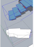
Removing walls from tube
 I double-clicked the group in this animated GIF. That should prepare it for editing. However, I cannot isolate only the area within the rectangle that I drew on the tube.
How do I prevent geometry beyond the rectangle from being deleted?
In the past I have been able to remove walls from a tube. This time it will not work and I can’t figure out why.
This is how I THINK I did it before:
 Group the box.
- Draw a rectangle representing the amount of wall I wish to remove.
- Double click the box.
- With the Select tool, I double click on the box.
- I clicked within the rectangle and then pressed the Delete key.
- This time the entire tube disappeared.
This time I added a rectangle with the Rectangle tool like it said online. There was Z fighting.
What is the proper way to delete part of a wall?
Z Fighting
 This animated GIF is a example of z-fighting. As I scroll my mouse button to make the end of the hexagon larger and smaller, the brown and orange colors are fighting for the same space they share.
The question is: How do I eliminate this z-fighting?
The answer was given to me on the SketchUp forum. Here’s what I was told:
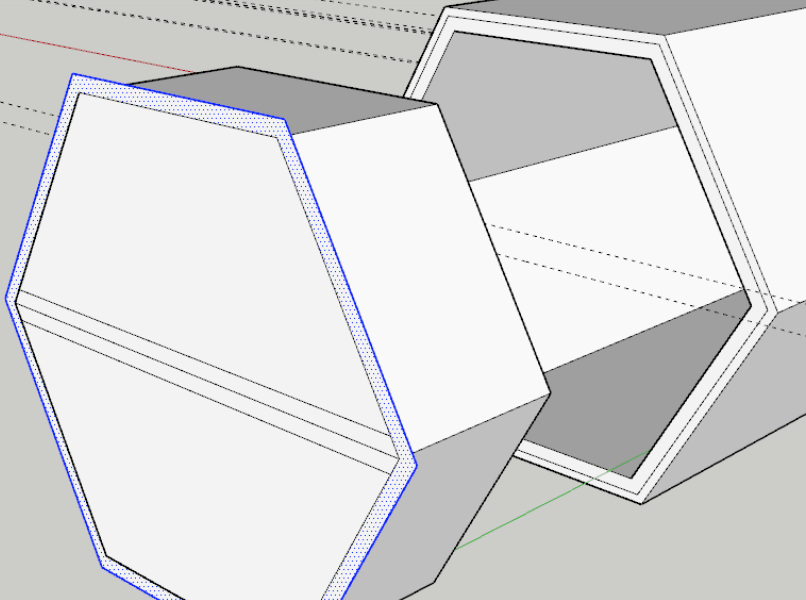 Z-fighting is an artifact of OpenGL when two faces are sharing the same location. The graphics card can’t figure out which face is supposed to be in front of the other. Remember that faces have no thickness. In your model there’s a sort of zero-thickness flange around the ungrouped geometry in the end of the hexagonal tube. Here I’ve moved that ungrouped geometry out so you can see it.
 The fix is to either remove the face or to give the flange thickness and move the face on the tube back. I’ve done that here.
And no Z-fighting when the two are placed together.
How Do I Make a Hold in the Wall?
 I’m trying to make a rectangular hole in a wall that has 2 layers. Push/Pull did not work.
I selected the portion that was to be removed and press Delete. That did not work.
So, how do I make a hold in a double-thick wall?
The link to the skp file can be found here: [Tube LH 7.skp|attachment](upload://jI0JRGnuPWar6YNZRFhw9UJVBf2.skp) (200.2 KB).
Colours change as Orbit cursor moves
When I look straight into the hexagon, the colours are perfect. When I use the Orbit tool, the colours start moving. Is there way to stop this?
The man from the forum said: You need to understand context,
You are getting z-fighting which is two faces fighting for graphic dominance. This is because you have created faces that are outside the ‘Group’ but basically in the same place.
Here you see:
- I triple click to select all the loose geometry,
- I then cut it to the clipboard, you won’t have this in your context menu, go edit/cut.
- Then I double click to open the group for editing
- and Paste in Place. (again edit/paste in place)
Getting your head around the concept of ‘Context’ is quite important.
Learning SketchUp Pro
 The section below has notes I was taking as I was learning SketchUp Pro from the free thirty-day trial. I have made this page mainly for my own benefit. When I’m not sure of how to do something, I can use Cmd F on my Mac to look for the key words to help me find a particular concept.
My First Drawing
- Note that you will make lots of mistakes. So, use Cmd Z lots to erase the previous action. Cmd Z will not work unless the Large Tool Set is in place as a vertical menu.
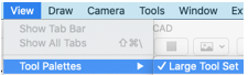 Go to View > Tool Palettes > Large Tool Set
- When you click on a tool icon, an animation of how the tool works shows up on the right if you have it setup.
- (I used the erase icon to erase the human that showed up in my new drawing.)
 Use rectangle tool to make a rectangle. In my Mac hold down the ALT key while drawing the first line. That way I can make the side parallel with the blue axis if I wish. Then type 4’ comma 4’ Enter to change it to a 4×4 foot rectangle. 2” thick
 Zoom. Turn the mouse wheel to make the image larger or smaller.
- To draw a permanent rectangle with the arrow pointer, first select Draw > Shapes > Rectangle. Alternately, use the rectangle tool beneath the pencil in the picture to the right.
- Use the push/pull toll to raise the rectangle.
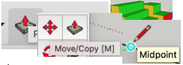 Draw a sloped roof. Using the pencil tool, find the midpoint of the edge of a rectangle. Draw a line to the opposite edge & move until the word “midpoint” shows up. Choose the Move tool. Hover over the centre line until you see the word “midpoint”. Drag the roof up.
- Making a Group. Triple click on the house. This will select each face, edge & point. Right click on the house & select Make Group. That will render the entire house as a single object. E.g., you can move the entire house up in the air using the Move tool mentioned above.
- As you move the house up, you can see a blue dotted line. After you see that, click 8’ to move the house 8’ up. If you move the house down as you are seeing the blue dotted line, the house moves down 8’.
- Use the arrows on your keyboard to determine which axis is used — up for blue, right for red and left for green.
 4 pillars to hold the house up. Pillars are 4” x 4” x 8’. Hold down mouse wheel and move to expose underside of house. Click on Rectangle tool and hold cursor on the Endpoint of the house with a rectangle showing on the underside of the house. Finish drawing rectangle and then something
 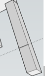 such as `4”,4” Enter to create the dimensions of the pillar.
-
- Use the Push/Pull tool to drag the pillar and make it longer or shorter. Alternatively: 8’ Enter.
- Click Select tool and triple click pillar so that it will move as a single unit. Right-click on pillar and click Component. (Thing that you will copy will be a
 component. Otherwise, you can Make Group.) With cursor at endpoint and Move tool selected, move pillar to opposite side. At some point hold ALT key down for a second. A second pillar will show up at the original point.
 - Click on a pillar. While holding Shift key down, click the other pillar. Now both of them will be selected. With
 Move tool selected, hover cursor over endpoint and move the two pillars to the opposite side. While doing that, hold down the Alt key to create a second pair of pillars.
 - Look at the aqua house above. It is now “complete”. To edit any part, you must
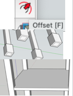 double click on that part with the Select tool. Double-click on one of the pillars to make it editable. Then select the Offset tool, click the bottom of a pillar and drag out to make a larger square. Type 2” Enter to make the base 2” offset from the pillar. Use the Push/Pull tool to create the 1’ high decorative piece around each base. Start Pulling up and press 1’ Enter.
 - Inferencing: To draw accurate measurements without ever having to enter any numbers. In this exercise, we will draw a platform of which the edges are flush with the 4 pillars. This is how to do it.
 Notice these 2 drawings with the rectangle tool. The top one has the pillars at not much of a slant and the picture will be a side view of the Rectangle. The bottom one has the pillars at a great slant and the Rectangle tool makes an image of the top of a rectangle.
- Using the Rectangle tool, draw a rectangle inside the pillar space. Using the Push/Pull tool and the 4” Enter sequence, change the rectangle into a 4” high platform.
- Triple click on the platform and right-click to make it a group.
- Click the Move icon and the click the lower corner of a pillar. This will allow you to easily move the platform up 32”.
 Tap the up arrow key to lock your move to the blue axis. Using the Move/Copy tool and a 32” Enter sequence, raise the platform 32” above the base.
- Using the Select tool, double-click on the platform to make it editable.
- Using the Push/Pull tool, click on each of the FOUR faces of the platform and drag them towards the appropriate pillar. Drag your cursor to the appropriate location on your pillar to which the
 platform should go. Look at the text like in the screenshot here.
 - Two opposite sides will run right through to the outside ends of pillars. For the other set of platform ends, use the Rectangle
 tool to join opposite corners of the edge. You will see the tiny word “intersection” at the 2 ends of the rectangle. Then pull them forward. Notice how the red line is at right angles to the face as you start making the platform.
 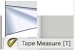 ARCS & CIRCLES. Using the platform from paragraph
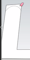
#6, you will use the tape measure to measure 1” and then 3” away from an outer edge. (To make the first line, attach tape measure to edge & then key in 2” Enter.) The will give you a space in which to insert a 2” wide wall. Using the Rectangle tool & the Push/Pull tool, draw a wall to protect the kids on this playground equipment.- Using the 3 point arc tool, draw an arc near the top of the wall. (Make sure you start the arc at the intersection of the pillar & the wall, NOT on the pillar.)
 The 7 points below are extraneous materials that I was learning about how to build the curved wall and the empty circles. Now all you will need are the sub-points below.
-
- Move the cursor to a point where the wall and the pillar meet. The cursor must touch the wall and NOT a pillar.
- Click the cursor like you see the red dot and then again somewhere in the middle.
 Press the mouse wheel and move the wall so that you can see the space between the wall and the pillar at the point where your third cursor point will be. Then click to create the end of the curve.
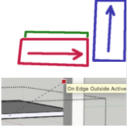
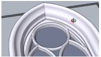
 - Hold the Push/Pull cursor on the upper curved section of the wall. Notice how it has multiple blue dots and the section below does not.

- Slowly move the cursor to the right & left until you are able to see a blue & white area like you see in this image. You may have to move right & then left.
- If you are having trouble with #4 above, try moving the Push/Pull cursor until the words “On Edge”.
- Push the upper section in so that it disappears.
- Using the circle tool, make a number of circles in the wall. Then gently move your cursor until the blue & white area appears. Lift your finger off the mouse button. The holes will appear & you can see the pillars or whatever is behind them.
-
- Keep moving the arc around until you see what you like and click. To start drawing the arc, click once to create the beginning, move cursor and click to make a point in the
 middle. Then move the cursor to click and make the end point.
 - You have been using components so that’s good. You’ve drawn the arc outside of the apron component, though so the arc doesn’t divide the face into sections. Before you draw the arc you need to open the component for editing. Double click on it with the Select tool to open it. Then draw the arc, get the Push/Pull tool and push away the area under the arc.
- Here I traced your arc while I had the component open. After I pushed the area under the arc I closed the component to get out of edit mode and deleted your original arc.
- The note below is from the SketchUp Forum (https://forums.sketchup.com/t/i-can-t-cut-push-pull-out-an-arch/154069/16) You should open the component for editing before drawing the curve so the curve will modify the geometry inside the component. At the stage of your model in the video, you could select the curve, use Edit>Cut to cut it to the clipboard, open the component for editing and use Edit>Paste in Place to paste the curve inside with the rest of the geometry. Then use Push/Pull to push away the waste.
- Start Push/Pull. If type in 5’, you can raise shape exactly 5’. Add 5’ again & you can raise it exactly 10’. Push/Pull works perpendicular to the surface your cursor is on. Push/Pull remembers the last distance you used. Double click on the next surface & it will expand to the same distance your previous surface did.
- When you use the Push/Pull tool to extrude a 2D face that includes an arc, SketchUp extrudes a special surface entity whose radius can also be edited. Use the Move tool to reposition the midpoint edge, and all the geometry that makes up the extruded arc will move accordingly, as shown in the figure.
 Free SketchUp plugins: https://sketchucation.com/pluginstore
- ARRAYS. Arrays are groups of identical objects in different locations. In this illustration we will create a horizontal bar. Then we will the array function to create 3 more identical horizontal bars.
- After selecting the circle icon, hover on the midpoint section of the pillar
 for 2 seconds. Move straight up by watching the blue dotted line and create a 1” radius circle on that dotted line.
 - Using the Push/Pull tool, move that circle across to the opposite pillar.
 Triple click on the bar and right click to make the bar a component. (That’s because you should always use components if you wish to make two or more copies.)
- Arrays are created by making one copy first. Use the Move
 tool to raise the bar along the dotted blue line to make sure it goes straight up. (You may have to press the Up arrow to make sure the line is blue.) Tap the Alt key to make a second copy. Beside “Distance” in the lower right-hand corner, type 8”. After the 8” (the distance between bars), type 3x and then press the Enter key. This will make 3 bars 8” apart. If there are too many bars, simply use the Move icon to move them beyond the pillars. Then use the Select arrow to select them and press Delete to delete.
 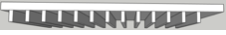 To create the 13 floor joists, I created the first one. It was 1 15/16” wide. Then I measured the distance from the first to the approximate distance to where the last joist would be. It was a little over 8.5 feet. That’s a little over 8 x 12”. I made the first joist into a component, clicked Move on it and moved it a bit. Then I pressed Alt to replace the one that had been moved. I pressed 8” Enter. Then, with the 2nd joist selected, I typed x12 Enter. Now I have a total of 13 joists. Notice that I did not fill up the space for the last 0.5”. So, I will have to add a 14th joist.
- After selecting the circle icon, hover on the midpoint section of the pillar
 This is how to make the array in the animated GIF to the right:
- Have 3 objects on the left hand end of the sidewalk.
- Using the Select tool, envelope all 3 objects going from left to right.
- Click on the Move tool and press the left arrow to move along the green axis.
- Drag your objects to the right.
- Press the Alt key (in a Mac or Ctrl in Windows) to reproduce the set of objects in the original position.
- Enter this in the Direction box in the lower right hand corner. (This will produce 7 equally spaced sets of objects after the first one.)
- Below is the response from the SketchUp forum regarding my inability to make steps.
You’ve got a couple of things going on, all related to the correct use of groups.
The ‘block’ itself is made of two groups, one the bottom and sides the other the top. This is no use in this case. The blue ‘bounding box’ is the giveaway that the geometry is grouped, if not grouped the face would show selected.
The edges you have drawn for the stairs are ‘Outside the context of the group’. Meaning you have not opened the group for editing before creating those edges and therefore they are not cutting the geometry of the ‘block’.
In this vid you can see that I am able to move the top away as a separate piece. I can then select and cut the edges to the clipboard, then open the group for editing and after drawing in an edge to heal the top I use paste in place to put the edges back. Then I’m able to push the geometry because everything is in the correct context. Note I have cut and paste in the context menu for display, you’ll have them in the edit menu or keyboard shortcuts.
 Steps. We will now create steps to go up to the platform:
- On the edge of the platform, draw a rectangle from the midpoint to the pillar.
- Use the line tool to draw a line to separate the steps from the rest of the platform. After finishing one line, click on another tool to turn off the line tool. Alternately, you can press the ESC key.
- With the Push/Pull tool, pull the rectangle out exactly 4’.
- Push/Pull down even with bottom of pillar.
- Note: You group the block AFTER the steps have been drawn. With the tape measure tool, draw dotted lines 12” across and 8” down. Alternately, you can start the line and type the length of the line desired. The numbers will automatically show up in the dimensions box.
- With the Line tool, draw a line straight down 8” from the 12” point.
- Go to edit line and choose Edit > Delete guide.
- Using your Shift key, select the 2 step lines.
- After the steps have been drawn, use the Push/Pull tool and select the section above the steps. Then push that space and isolate the steps. (You may have try this several times. Moving the tool down will move the steps in the wrong direction.)
 Use the 3-point arc tool to remove parts below the steps.
- Group the steps.
- On the edge of the platform, draw a rectangle from the midpoint to the pillar.
- The Slide. Draw rectangle about 2.5’ wide on unused side and drag it out 6’. Then drag it down to ground using pillar as reference.
- Using a 2-point arc tool, draw an arc from about 4” below upper right-hand corner.
- Select arc and Cmd C. Then Cmd V to paste it. Move mouse around and
 you will see the blue arc. Move it so RH side is in the corner.
 - Using the Push/Pull tool, remove the spaces above & below the arcs.
 Then Group the slide.
- Add shadows to slide.
- Add Colors to slide.
Core Concepts
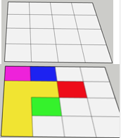 In SketchUp we basically work with 2 different concepts: edges & surfaces.
- To be able to join edges & surfaces, they must be coplanar. I.e., they must be on the same plane. Notice in this drawing of 16 rectangles, they were made by connecting midpoints on the same plane.
- By erasing lines, we were able to change the shape of the surface. Note that the paint tool will paint all areas of a surface unless the surface has been interrupted by lines.
- Those small rectangles could not be created unless the surface was coplanar.
- A fast way to erase multiple edges is to hold the mouse key down and drag the eraser over the
 edges. When you release the mouse button, all selected edges will disappear.
 - The erase a surface, click the Select tool on a surface without touching a line connected to the surface. Then press the delete key.
- If we hover over a point on an edge with the line tool for 2 seconds, SketchUp will remember that point. Then we can draw a line to approximately where we thought the point was. It will have some text such as “On Edge” at the exact point where we hovered.
- Inference points include midpoints, endpoints & edge points.
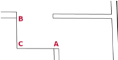
- I started at the RH edge to draw line A. When I got to point B, I stopped for 2 seconds and then continued drawing. Next I started at point D and began drawing another line. B was already an inference point. So, when I got to point C, the dot at line B showed up and I could have gone up the green line and drawn a line straight up to point B. Then angle BCD would have been a right angle.
- Note that the lines must be continuous to create a surface. In this tiny sample, the line above & to the left of the LH red rectangle has been erased. Consequently, the color has been eliminated from that shape.
- Here I’m drawing a box using inferences and my Line tool. The 15’ x 15’ rectangle will be the top of the box. I’ve already made one side. To make the next side I clicked on point C below B, moved my cursor up to the endpoint near A and hovered for 2 seconds. I returned the Line cursor to below B and
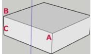 drew a line along the green line until the endpoint at A was highlighted. I clicked the mouse and went straight up the blue line until I could click on A. The result is the new box you see here.
 - CAUTION: Sometimes when the angle of a shape is wrong, 2 of the lines (in this image it is the red & the blue lines) may almost overlap.This can
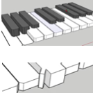 cause mistakes. If that happens, press the mouse wheel to change the angle of your shape.
 - Pull identical heights. When you want 2 or more shapes to be pulled up the identical heights (like these piano keys), raise the first one the desired height. Then double click the Push/Pull tool on the other shapes to be pulled out the same height. You can also double-click the same object to let a side panel or part to be pulled out the same amount as the height.
 X-Ray — To be able to see both the outside & inside wall at the same time, click on View > Face Style > X-Ray.
- Copy of old wall — If you are dragging up an 8’ wall to become a 10’ wall and you want to see what the 8’ wall looked like, click the Alt key.
- To draw with the Line tool, start drawing and lift the mouse button. Then enter the desired length in the Length box. Press Enter and you will go to the correct length.
 When I drew this triangle, it said “end point” at each vertex. That is why I was able to paint it green without painting anything else green.
- Change default measurement units — Presently my default units are inches. So, if in the length box I enter 48 Enter, SketchUp will draw a line 48” long. To change the default units, go to Window > Model Info.
- Arc tool — To make an arc of a specific radius and a specific number of degrees, use
 the Arc tool & drag it to the canvas. Set the radius in the measurement box. Then start dragging your arc & release the mouse key. Then enter the number of degrees in the measurement box. Click Enter.
 - Tape Tool guide lines — Good example of using Tape measure guide lines is 30” from each edge and so much from top & bottom of wall to place a window. Then use the Line tool to draw the window.
- Polygon tool — If you want a polygon 4’ in diameter with 7 sides, start to make the polygon and then type 7s 4’ Enter. That gets entered into your dimensions box and shape is immediately created.
- Difference polygon & circle — You can create a polygon by entering 7s 4’ Enter and get a circle that sort of has 7 sides. However, the polygon is the only one that will have 7 very distinct sides when you pull it out with the Push/Pull tool.
- Hendecagon (11-sided figure) — To make a hendecagon with a
 5’ radius: Click with Polygon tool & type 11s 5’ Enter
 - Colored faces — To color each face of a polygon, Select & double-click. Then apply colours.
- Arcs
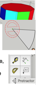
- Pie — Move the protractor so that it’s flat. Click. Drag out. Start to drag the line down. Type number of degrees and then click Enter.
- Protractor tool — Set your protractor on the origin of the angle you want and click. Slide your cursor from there, drag out your cursor to a convenient point on your base line and click. Arc your protractor to, say, 45 degrees (the protractor has 15 degree increments) and click. Use the line tool to draw a new line over the dotted line.
 2-point arc — Click on 2 points. Go to middle of straight dotted line between them. Drag midpoint out to create an arc.
- 3-point arc — Click, move cursor & click again, then move to shape arc. Click to save a shape.
 Freehand tool — is not incredibly accurate for drawing lines.
- Pie — Move the protractor so that it’s flat. Click. Drag out. Start to drag the line down. Type number of degrees and then click Enter.
- Entity Info — To find information about a selected shape, click Windows > Entity info. It will give you the area, radius & number of sides of a shape.
Rectangles
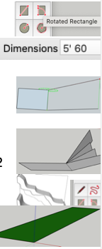 Notice some of the things you can do with the Rotated Rectangle tool.
- Click on 2 points then enter 5’,60 meaning 5 feet and 60 degrees. (If you rotate your image to look at the side view and use the Pie tool, you can check and it will be exactly 60 degrees.)
- Click 2 points and then move out at a particular angle. Hold shift key and I can extend it as far as I want at that particular angle.
- For each of those 4 rectangles on the right, I clicked the 2 RH corners of the left rectangle. I dragged the cursor out without clicking. Then, for each of the 4 samples, I went 4’,60 Enter; 3’,45 Enter; 3’,30 Enter and then 4’,15 Enter.
- I started this green rectangle by starting at the origin of all 3 axes and then dragging along the green axis.
2. The Freehand tool is not incredibly accurate.
3.  The Offset tool in this example was used to make another copy of the arc. With Offset tool selected, click mouse on edge of arc. Key in 3” Enter.
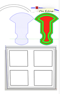
Note the irregular shape on the left. Then, using the Shift key & the Select tool, every edge was selected. Click Offset tool onto selected edge and DRAG it towards the inside. After having done that several times, I made the red & greed design.
To make these 4 window panes I created the outside rectangle and then offset it twice to make 2 rectangles inside. Then I used the Measure tool to find location of windows. I saved the frame as a group. Then I made one pane and saved it as a component. Using the ALT key, I duplicated the second pane. Using a similar system, I created that second set of 2 panes.
Eraser
- It only works on edges; it will not erase surfaces.
- To use Eraser, hold down mouse button and move over as many edges as you want.
- Notice small circle on LH corner. That’s focus area. Hold over line that is to be erased.

 In LH area of window, held down shift key while erasing and edges were erased. Shadowing stayed. In RH side, ALT key was held down to soften the edges. Note that the shadow was also softened
Selection Methods
 For more information, search for a lesson titled Selection Methods.
- To select a line or a surface, click on that line or edge.
- If you double-click on a surface, it will also select all of its bounding edges.
- To select a line, a surface AND the grouped geometry, triple-click on a surface or edge.
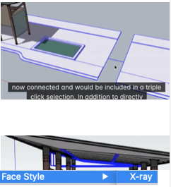 To connect all grouped geometry in 2 separate surfaces, temporarily draw a line connecting those surfaces. Then triple-click.
- Selecting groups of objects.
- To select a group of objects, drag a rectangle from LEFT TO RIGHT around the objects. Only those objects within the rectangle will be selected. However, if you drag the rectangle from RIGHT TO LEFT, anything the dotted line touches will be selected.
- Sometimes you may select a rectangle on top of a roof and accidentally select the objects below the roof. Use View >
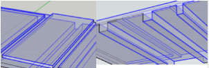 Face Style > X-ray to see what is on both sides of the roof at the same time.
- Modifiers
- Shift key to select objects at more or less the same time.
- Alt key to add items such as when I use the Array concept.
- Alt-Shift together will only subtract.
- Select > Delete will also subtract
Grouping
 Grouping Concepts
When edges touch or overlap like this table & wall, they become one like this table & wall. Notice how it pulls the wall out to the right. You prevent 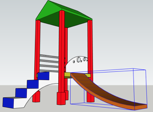 this sticky geometry problem by grouping. Use the Select tool to draw a rectangle around all components of the table that you wish to Group. Then right click to group.
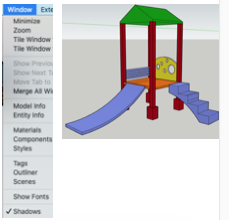
 Notice the roof on this slide set. It is a group. If we select it, we can use the Move tool to move it. To edit a group such as the roof, you would
  have to double-click it with the Select tool. Notice
 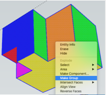 how we were able to change the roof color to green by double-clicking on it.
When making a new shape, group it as quickly as possible to prevent sticky geometry.
 Nested groups are groups within a larger group. For instance, each stair is a group. The set of stairs is a larger group.
When we form a new shape, it is best to line it up with the red, green & blue axes. In this example, the shape was NOT lined up with those axes. That can make editing more difficult.
 In this example, the shape is not lined up with the axes. This is how to line the shape up properly. Then it will be easier both to edit and to work with inferences.
- Select group, right-click on group and choose Place.
- Click 3 times. The first to establish the base of your new axis. The second to establish the red direction. The third to establish the blue & green directions. The shape is now better aligned with the axes.
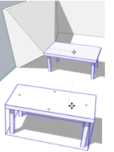
 Rotate a group — Select a group such as this green roof by clicking once. Click on Move tool and hover over roof. Hold cursor down over red marks and you can rotate it.
Edit a group — To edit a group such as this roof where I added a red chimney, double click on it. Then edit like you would normally edit something.
Cut a piece out of a box — To cut a piece like the example, simply use the Line tool to draw 2 lines. Then use the Push/Pull tool to push it down.
Nested groups — In this image, the stairs as a whole is a group. Each individual stair is also a group. You can edit each individual stair by double clicking on the group as a whole & then double click on an individual stair.
Line up with 3 axes — The dotted line in the image is lined up with the red, green & blue axes. However, the geometry in the image to the right is not lined up with those axes. Bad idea. That makes it more difficult to do some types of editing such as inferencing.
Copy before editing — In this image we wanted to edit the wall. So, selected 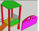 it and then clicked Edit > Copy. Then we pasted it elsewhere. Note that this will work for groups but not components.
Components
In some ways components and groups act the same: They both can act as single objects, be moved, copied & be rotated.
Click on Window > 3D Warehouse. You will see an online warehouse that has MILLIONS of user-created samples of things. Because there are millions, you have to be specific in your searching. Note that some things are very detailed and will slow down SketchUp.
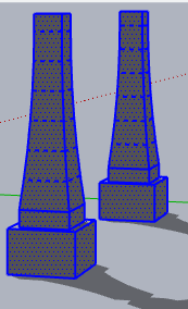
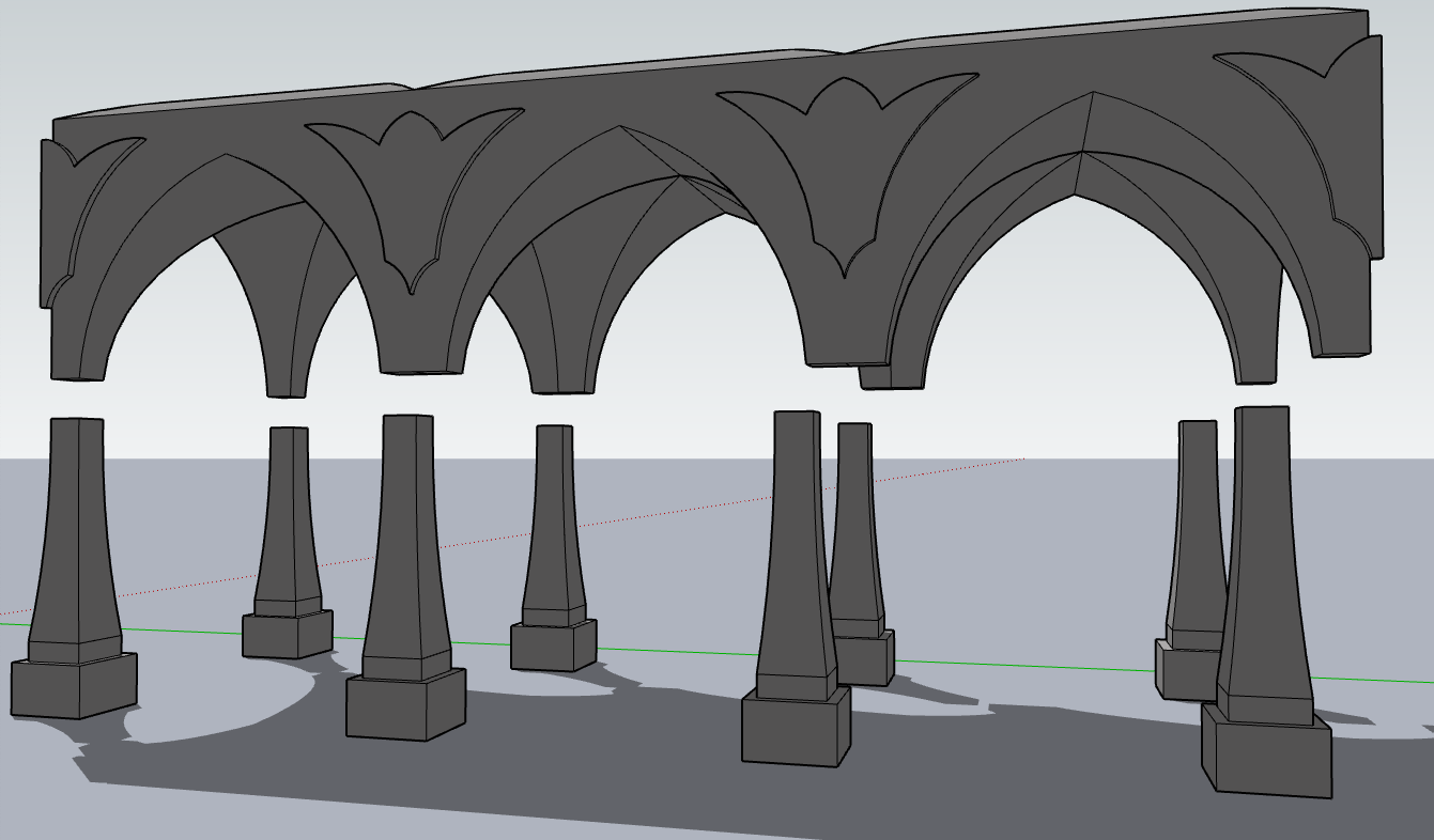
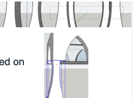
 In this example we will create this structure of arches and then have it supported with 8 pillars that are all components.
To create the structure: Using the Rectangle & Push/Pull & tape measure tool, create a block that is 15’ (or a multiple thereof) wide. Draw guidelines on the roof, say, 1’ from the edge and add a rectangle. Use the Push/Pull tool to create a wall 1’ thick. On the long sides, use the Tape Measure tool draw 9 guidelines an equal distance apart.
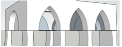
Using the 2 point arc tool, I drew the 2 curved sides of each arch. Then I used the Line tool to connect the corners of the walls to the bottom of each arch. I used the Push/Pull tool to delete all materials below the arches. I added complementary arches to the ends of the structure.
 I changed the structure to a group.
I wanted to have the structure upheld by 8 pillars. So, I created one relatively fancy structure and changed it into a component.
 After clicking the Move tool, I clicked onto the upper LH corner of the pillar and, using inferencing, moved my mouse cursor and clicked on the corner of the structure that you see in the illustration.
With the Move tool selected, I clicked on the LH corner of the pillar and moved it to the right a bit. Then I hit the ALT key on my Mac. Then I continued ![]() moving the pillar until I clicked on the lower LH corner of the upper structure.
moving the pillar until I clicked on the lower LH corner of the upper structure.
 With the Select tool, I held down my shift key and selected the 2 left-hand pillars. Then, after clicking on the Move tool, I held the cursor on the dot at the upper LH corner of the pillar. I began moving the pillar to the right. After about a pillar’s distance, I pressed the ALT key on my Mac to reproduce the original 2 pillars in the original location. I ended up moving all 8 pillars into position as you see in this illustration.
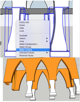 Using the Select tool, I drew a rectangle to the LEFT as you see in this illustration. This in turn selected the 4 inner pillars as you see in the lower illustration. I right clicked and chose Make Unique.
This means I can edit ONE of the 4 inner pillars and edit the other 3 at the same time. Meanwhile, the other (outer) pillars will not be affected.
The white are components. That means that when we apply something to one pillar it will have do happen to all of the others.
We have a problem. The LH pillar is a bit off centre. In order to be able to move it independent of 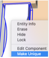 the other pillars, we click on it with the Select tool. Then right click and click Make Unique. Now we can move it without moving the others. Make Unique can also be applied to more than one pillar at a time.
Creating tiny components
(e.g., cabinet door handles)
Step by step instructions
 Draw rectangle
- Draw 2 parallel arcs within rectangle
- Color it the color of a cabinet door handle
- Erase the excess part
- Using the Scale tool,
- With Select tool, select the handle
- Click on the Scale tool
- drag a corner green square in to make the handle as small as possible.
- Using the Tape Measure tool, measure the length.
- If it is too big, start over with drawing a rectangle in point #1
- Use the Move tool to move the handle to a convenient place close to the cabinets.
- Whenever you need a handle, move it to the correct location. While doing that, press the ALT key to keep a copy in the original location.
Rotate
 Clicking the Rotate icon can place the protractor on any one of 3 planes — red, green or blue. Shift/Rotate will keep it on the same plane no matter where you move it.
Let’s say we want to turn this irregular shape to be parallel with the blue axis.
- I make it into a group.
- Then I click the Rotate tool.
- When I have a blue protractor, I hold down the Shift key and click on the LH corner.
- Then I click on the RH corner.
- Then I rotate so that the long side is parallel to the blue axis.
- Note that you can type in numbers to represent the number of degrees you wish to rotate.
Floor Plan
Red & Green directions are inference directions. Midpoints, edge points & end points are inference points.
 Hovering: When we draw a line, we want to click the mouse only at the 2 end points. In this example, we clicked at A and then hovered 2 seconds at B and then moved down until you saw inference point directly below at C. Then, directly to the left at C, I would click.
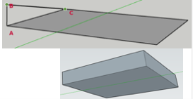 Drawing a box: To start drawing this box, I first draw the dark grey rectangle. Then I draw a line from A to B. Then I hover at C for 2 seconds. Then I draw right in the green direction until, directly above C, I see an inference point. I
 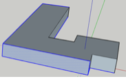 click and then draw a line down to C. For your exercise, finish the box with 4 sides around the initial rectangle. And then make an irregular shape.
Push/Pull to cut open a surface: The back of the surface must have a 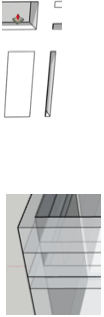 face parallel to the front and must be unbroken.
Push/Pull to cut open a small surface: To cut open a small opening, use inferencing. Hover your Push/Pull tool over the back edge of a nearby surface. The small surface is in the lower RH column and the Push/Pull tool you can see in another rectangle touching the back of an opening.
Multiple layers with Push/Pull: If you are drawing walls within a building, click on your Push/Pull tool and then press the ALT key. A plus sign will appear to the left of the Push/Pull tool. This means that when you add a foot or whatever to your wall, a drawing of the first wall will appear in your drawing. (Note that I used View > Face Style > X-Ray in my illustration here.)
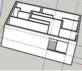 Cut window of specific dimensions & distance from edges: Use tape measure to measure distance from bottom & one wall. This will provide 2 guide lines. Use tape measure to use guide lines for distance to other edges of window. Use rectangle tool to cut out window opening.
Arcs
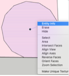 As a default, arcs are drawn with 12 sides. Each arc is made by clicking 3 times. This 3-point arc was started by clicking in a corner, on a side and then dragging the arc around. Right clicking on it and then Entity information will give the number of square feet.
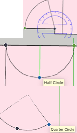 Pie tool — The protractor in the Pie tool will snap in 15 degree increments. The angle you see to the right is at 75 degrees.
2-point Arc — The 2-point arc will snap to a half circle. Remember that all arc points require 3 clicks. You click on either end of the 2-point arc, then shape the arc and make the third click to save it.
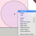 3-point Arc — The 3-point arc will snap at the quarter, half & 3 quarter circles.
Arches & Pillars
To make the arches:
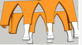 Took the outer part out of a huge block to create 4 narrow walls.
 - Used the 2 point arc tool to create the arches.
- Carved a pillar out of a block. The width was the same as the arch width. The length was not quite as long as the orange part between the arches.
- Made the pillars into components.
- Using ALT and other things moved two pillars to below the 2 end orange parts.
- Used the Rectangle tool to pull the end of the pillar out to match the bottom of the orange part.
 Used ALT to drag the pillars beneath the rest of the arches.
- Right clicked on two of the pillars to make them unique from the rest of the pillars.
- Then I drug them out so that the extension at the top of the 2 pillars pointed in the opposite direction of the other 6 pillars.
Nesting
We’ll take a number of groups or components and combine them into a single group or component. Then we can move them in unison.
 Click the Select icon and, moving left, draw a rectangle around the table & all 6 chairs. This will select all 7 items. Right click so that they can be made into a group and moved around as a single object.
Tags
Unrelated info.: In 2020 “Layers” were renamed “Tags”.
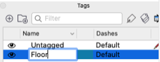 You open your Tags menu by clicking on Windows > Tags. Let’s say you are going to draw a house and start with the floor. Select the floor and click the plus sign in your Tags menu. Change the name of you new tag to Floor.
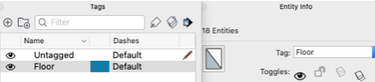 As you project continues, you will add walls, a roof, etc. So, you can have new tags called Walls and Roof. Note that their geometry will still be connected. So, if you change the shape of your floor
 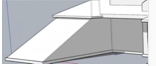 after the walls have been created, this will have an unwanted effect on your walls.
To avoid this problem, you can change each of Floor, Wall and Roof into a group. After that, making a change will not affect the geometry of your other features.
 This is my floor. I made it into a group, selected it, clicked the plus sign and changed the name to Floor. (Rename a tag by double clicking on it.)
- Triple click on the floor
- Click on Windows and open up both tags and entity.
- Click plus sign and name tag Floor.
- Click dropdown arrow in Entity Info and select Floor.
- Triple click the Floor and make it into a group.
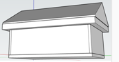 Now you can turn off the picture by clicking the eyeball.
Do that for all Groups. Then you can turn them on or off to edit them. With the house here the tags are floor, walls & roof. I made the peaked roof by drawing a rectangle 34’ x 24’ way above the walls. I connected the midpoints of opposite sides and then slowly moved the Move tool until I saw the word Midpoint. Then, moving the cursor in the direction of the line, I slowly created the peak.
Note that if you have too many tags, SketchUp will give you a warning.
Move Tool
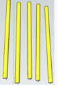 Rotate
The image to the right is called 5 Yellow Cylinders Vertical. This is how to make them lie horizontally.
- Using the Select tool, hover over one of the pencils. Notice the red plus signs at either end.
- Press red arrow so that it will rotate around it. Hold the Move tool over the plus sign and rotate the cylinder.
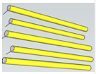 Do this for all 5 cylinders.
 - Drag the cylinders to an appropriate place. If a cylinder appears too big, that’s because it is too close. Press the left arrow to make cylinder move back along the green axis.
Move into Transparent Jar
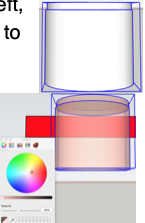 To move your cylinders into a transparent jar, you must first create a much larger cylinder & make it transparent.
- Using the circle tool, make 2 cylinders. Then use the Left, Right and Up arrows and the Move tool to move the lid to the top of the jar.
- Make sure they are selected.
- Click on Window > Materials.
- At the bottom of the color chart you can see a slider to change the opacity. Reduce opacity.
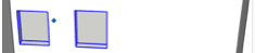 In this image the Move tool is being used to drag the last yellow cylinder into the jar.
 - One of the pencils was not touching the bottom of the jar. This is
 what I had to do:
- Select the 2 parts of the jar.
- Move them away from the pencils.
- Select the pencil in question.
- Move it down a bit.
- Move the jar back over the pencils.
Move Windows, etc.
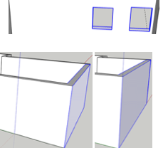 In the top image only the windows were selected. When they were selected, the Select tool was moved from LEFT to RIGHT!! Then we used the Move tool to move the windows along the green axis to the right. The same thing happened with the walls here. The wall on the right was the original one.
The geometry was NOT grouped yet. The end wall in its entirety was selected from LEFT to RIGHT. Then the wall was dragged out to the right with the Move tool. Thus that room in the house became longer.
Picture Frame
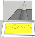
 I am trying to draw a picture frame using a rectangle. I want some fancy grooves. I used a 2 point arc tool, making sure I used the up arrow (blue axis) so that the arc would be on the side of the frame.
The same left to right selecting was used to increase the length of this picture frame.
Autofold
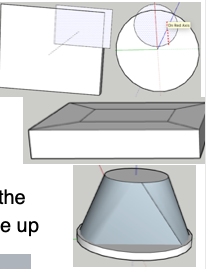 Here a circle was drawn onto the top of a cylinder and a rectangle was drawn on top of a box. When I tried to move them, they just went to the side.
Those circles & rectangles just stay on the same plane when you try to move them.
However, then you draw lines to the outer corners of the rectangle and also press the Cmd key while trying to move up the circle, you get better shapes.
 If you try using auto fold with complex curved surfaces, that can get too messy.
Arrays using Move

Use Move to create a complex array. These are the parts:
- Sidewalk — Rectangle tool entering these dimensions: 5’,100’
- Lamp pole — Up arrow (blue). Make circle with 2” radius. Push/Pull it up 10’. Make component. Double click on it. Using Offset tool, drag a circle beyond the radius of the pole.
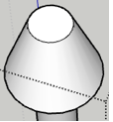 Holding the Cmd key down, drag the smaller circle up to create that cone effect. Make the whole thing a component.
 - You will likely have to use your left, right and up arrows. Drag the post to the left corner of the sidewalk.
- Park bench — Entering 2’,5’, draw a rectangle and Push/Pull it down around 3’.
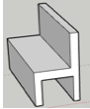 Push/Pull rectangles to create the seating part and the space between the legs.
- Use similar rectangles on the front & back to finish off the legs.
- Using the Line tool & the centre green spots, connect the centre spots to create 8 slats on the seat and 8 slats on the back.
- Make the bench into a component.
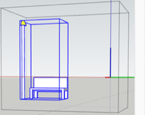 Make the array down the sidewalk — Using your Up, Left & Right arrows, move the bench to the right of the lamp post. Holding your Shift key down, select both the lamp post and the bench. Right click to make the pair a component. Press you Left (green) arrow.
- Using your Move tool, move the lamp post & bench to the right. Key in 6’ Enter. Making sure you are not holding any keys down, enter “15x Enter”.
Follow Me
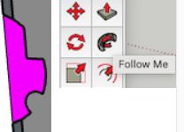 Often best to preselect a path first. Hold the Shift key in and, with the Select key, preselect every line that you want the molding to follow. The opening image, like the magenta one you see here, can be a small distance away from the selected path.
 After the path has been selected, click on the Follow Me tool and then click on the opening image. The molding will follow the preselected path almost immediately.
Your opening image has to be perpendicular to the path it’s going to follow. One easy way to make sure that happens is to make a rectangle with the depth extended a bit with the Push/Pull tool.
![]() Then, on the face of one of the edges, draw an interesting shape and colour it. Select your rectangle with your Select tool. This will create a
Then, on the face of one of the edges, draw an interesting shape and colour it. Select your rectangle with your Select tool. This will create a  path around the entire rectangle. Click the Follow Me tool and click on your opening image. You will see a rectangle like the orange one to the left.
 Notice this kitchen island on the left. The curved line has been selected with the Select tool. On the right I had used the Follow Me tool to make space for people to sit under the counter.
In order to make a kitchen more ergonomically safe, it is common to add a 4” x 4” toe kick at the bottom. Do NOT use Follow Me for 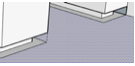
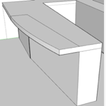 this process. If you do, you will end up cutting out too much. For example, the ends of counters commonly do NOT have a toe kick for aesthetic reasons.
Instead, draw rectangles and use the Push/Pull tool.
In our example we had a counter top that begins a curved surface after a few feet. Do NOT use the Follow Me tool to remove space to set the stools beneath the counter. Otherwise you cut away too much.
Instead use the Push/Pull tool to remove the portion that is straight. The use Follow Me to remove the space beneath the curved section. Make sure you create a temporary shape on the counter section that includes the curved section. Then use your Erase tool to remove excess parts.
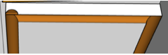 In order to make the decorative portion of the cabinet door in this image:
- The rectangle had to be pulled out far enough to accommodate the 2 Point Arc.
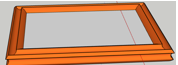 The rectangle that was to be decorated had to be selected.
- The arc for the decoration had to be coloured orange.
Walking through a model
To watch a video about how to make a Walk Through animation on an MP4 file for your client, go here. See a sample MP4 file of a Walk around the exterior of a house, go here. See a video about creating a SMOOTH walk around the exterior.
I went to the SketchUp help pages and found the information below.
Here’s how each tool enables you to tour your model:
- The Position Camera tool (
 ) enables you to view your model at a specific height relative to the surface of your model. That height is meant to reflect a person’s eye height, and you can adjust it to any height you like.
 - The Look Around tool (
 ) enables you to move the camera from side to side, sort of like turning your head.
 - The Walk tool (
 ) moves SketchUp’s camera forward or turns it in different directions, which simulates how your model looks from eye height.
 At this point my 30-day free trial is finished. As I’m waiting to buy SketchUp Pro, I’ve been looking at videos. Consequently, I’ve made several decisions:
-
- VRay costs around 1000 CAD per year. I’m NOT going to buy it.
- I watched 3 very important videos. Do not watch them until you are finished the free 30-day trial. They’re about how to make a kitchen, how to make a bedroom and how to make a living room with SketchUp Pro. The three most important things I
 learned are
- I probably know half of the things that are in those videos already.
- The things like textures, reflections and components such as plants, windows and couches are already available with SketchUp Pro. I do not need to get Vray in order to create really professional 3D animations.
- The bedroom video shows a lot about adding lights, reflections, etc. I have not seen them yet in the course. After watching the bedroom video, try to find
 the videos that explains the lighting techniques.
Another important consideration: Should you buy SketchUp Go for $119 or SketchUp Pro for $349?
The free trial is SketchUp Pro. I’ve seen SketchUp Go and it is vastly inferior. I have no idea why anyone would buy it.
Another point: Go to this video to see many SketchUp tips that many people don’t know about.
